
Specification
1. What is a Ball Valve?
Generally, valves are components used to control the flow of water, oil, and other liquid through a closed hydraulics system. Flow-through a valve will be relatively unobstructed when it's completely open. Flow stops when the valve is totally closed.
A valve consists of a valve body with a rotatable ball within it. This ball or sphere features a hole or bore through its centre. The handle on a valve opens the valve when it turns the ball to align with the pipe or tube system. This enables flow to pass through it. The valve handle may also turn to the right or 90 degrees angle of the flow, this will put the valve in a close position.
Ball valves still close securely even after a long period of not being in use, it is tough, durable, and reliable. These qualities make them an exceptional choice for shutoff and control hydraulics applications.
2. What is a full-bore and reduced bore?
Full bore ball valves have larger bodies as compared to standard valves. This larger body consists of a larger ball and an opening inside. Full bore ball valves have the same openings size as the surrounding piping system. For example, a 1” full bore ball valve will be compatible with a 1” pipeline and it will have a 1” ball valve opening inside the ball. These are applications that require very little to no flow loss. When a full port valve is “on” or open position, its flow is unrestricted.
Apart from full bore ball valves, there is also what is called a reduced bore ball valve. As you may visualize, this means that the opening of the ball is lesser than full bore ball valves. In fact, it is exactly one pipe size smaller. For example, a 3/4” reduced bore ball valve has only a 1/2” pipe size ball opening. This smaller opening resulted in an increase in velocity.
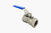
Reduced Bore

Full-Bore
3. How is a three-way ball valve different from a two-way ball valve?
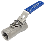
Two-way ball valves are generally used as shut-off valves for gases or liquids moving through tube or pipe systems, mainly due to their simplicity and reliability. Two-way ball valves have two ports where pipe or tubing is connected to both ports of the valve. The ball in two-way ball valves has a single straight hole through it where the liquid or gas flow through the valve.
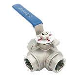
Three-way ball valves consist of three ports or connections for use of a tube or pipe system. In general, three-way ball valves can solve more complex flow control needs as compared to two-way ball valves. This makes them useful for various types of process system applications.
For example, a three-way ball valve design could divert fuel flow from one tank to another tank while also being able to shut off the flow of fuel entirely if required. When choosing a three-way ball valve, it is important to understand key three-way valve design options and plan on how the valves will be used.
4. What is L-Port Ball Valve?
L Port Ball valves, also known as 90-degree ball valves are most often used to allow flow from one common inlet port into one of two separate outlet ports. This is why L Port three-way ball valves are also often called diverter valves.
Diverter or directional valves are another names for L-Port ball valves as this valve design is widely used to divert or change the outgoing flow through one of two different valve outlets or ports.
L-Port flow ball valves with handles that turn 90 degrees (a quarter-turn of the handle) are also referred to as two-position valves. They are normally used for diverting flow either to the left or right with a 90-degree turn of the handle.
Three-position L-pattern flow ball valves
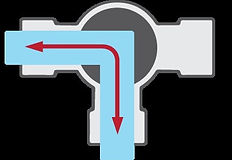


Three-position three-way L-flow pattern ball valves have a 180-degree limit on the turn of the handle.
In this design, the handle position could start with a clear flow path between the bottom port and the left port. Turning the valve handle 90-degrees counterclockwise to its second position allows flow through the valve, but this time the flow is between the bottom port and the right port.
Turning the valve an additional 90 degrees counterclockwise, 180 degrees total, cuts off all flow through the valve. These sort of L-pattern flow ball valves are usually called three-position valves: a starting position, a 90-degree turn, and a 180-degree turn.
5. What is T-Port Ball Valve?
T-Port flow balls valves, sometimes called 180-degree ball valves, are widely used to connect two inlet flows and combine them to flow out into one common outlet port. Depending on requirements, the reverse is also applicable which is split the flow coming in from one common port into two outgoing flows, each exiting the valve through a different valve port.
T-Port flow ball valves are not just suitable for splitting or dividing flow. They are also able to use like L-Port flow ball valves which divert flow from one outlet port to the other.
Like L-Port ball valves, T-Port flow ball valves change flow paths with a quarter-turn of their handle. Depending on the array of handle motion, they can provide diversion flow, mixing or split flow, and straight-through flow.
On an important note, T-Port flow ball valves are very different from L-Port flow pattern ball valves. Typical T-Port flow ball valves unable to provide shut-off control. They can only either limit flow to two of the three-valve ports or allow flow through all three of the valve ports at the same time. This is the main reason why T-Port flow pattern ball valves are sometimes called as mixing valves.
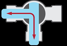


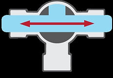
Mixing valves are among other names used for T-Port flow ball valves. Mainly due to the valve design being widely used to mix or combine flow coming from two different sources. Manual three-way T-Port ball valves used for mixing valves are usually installed with the bottom part of the valve body as the common outlet port.
Similarly, for the L-Port flow ball valves, each 90-degree turn of the handle changes the flow path flowing through the valve. And like the L-Port flow ball valves, the turns of the handle may be limited by the design of the stop handle.
6. What is the difference: One, Two, and Three-Piece Ball Valves?
1. One-piece ball valves
One-piece ball valves are inexpensive and generally replaced instead of repaired. It has a solid and cast body which reduces the risk of leakage.
2. Two-piece ball valves
Two-piece ball valves are some of the most commonly used ball valves in a hydraulics system. As the name suggests, a two-piece ball valve consists of two pieces, one piece has one end connected with the body, and the second piece fits into the first and holds the trim in place that includes the second end connection. Two-piece ball valves once installed are typically non-repairable unless they are removed from service.
3. Three-piece ball valves
Three-piece ball valves as the name suggest manly consist of three pieces; two end caps and a body. The end caps are usually threaded or welded to the piping system and the main body section can be easily removed for cleaning or repair purposes without the need to remove the end caps. This is a very valuable option because it prevents a line shutdown during maintenance.
HOW TO INSTALL A THREADED END BALL VALVE
*** The flanged ball valve with a lever handle can be installed at any position on the pipeline installation in any orientation.
STEP 1
Inspect the ball valve ports, seating surfaces, and threads to ensure they are clean and free of foreign debris.
STEP 2
Operate the valve from fully open to fully closed position.

STEP 3
Ensure the threaded pipe connections to be threaded into the valve are accurately threaded, clean, and free of foreign material or metal shavings.

STEP 4
Apply a high-quality pipe thread sealing compound or PTFE thread sealing tape following the manufactures application instructions to ensure a leak-free pipe joint seal.
%20BSPP%201a%20300px.png)
STEP 5
Valve and piping must be in alignment to prevent cross-threading, the male threaded fitting needs to be aligned with the axis of the tapped hole.
%20%201a%20300px.png)
STEP 6
When installing two-piece body ball valves always use two wrenches when making up pipe joints to these valves.
STEP 7
Tighten until you can feel the joint starting to seat and the fitting is almost pointing in the desired direction. Then increase the tightening force a little if each attempt gives less movement, continue to tighten until you have proper alignment and you should have a sound joint.


